
Friday, September 10, 2010
In This Issue:
Feature Article - FANUC History in North America
Compensation: Looking for more accuracy from your machine tool?
FANUC Tips & Tricks
FANUC History in North America
General Numeric Corporation, a partnership between FANUC & Siemens A.G., was established in 1976. General Numeric's mission was to supply new control systems for installation on new machine tools produced in North America (serving the OEM market).
Realizing that support was crucial in the US market, FANUC also established FANUC USA Corporation in 1977 to support FANUC hardware on machine tools imported to North America form other countries (mainly Japan at the time). Prior to this, North American machine tool importers and distributors were responsible for supporting FANUC hardware.
In 1986 FANUC partnered with GE to form GE Fanuc, thereby ending their partnership with Siemens, dissolving General Numeric and terminating GE's sales of its own GE2000 control. GE Fanuc was mainly responsible for selling and supporting FANUC control systems to OEM's and retrofitters in North America. Oddly enough, Siemens would eventually become one of FANUC's biggest competitors in the US. The GE Fanuc joint venture lasted until 2009 when it was dissolved and FANUC CNC America was formed, combining the control systems sales of GE Fanuc with the support side of FANUC America. Today, this one company sells and supports the entire FANUC product line in North America.
Control & Drives History
220 SERIES
In 1960, FANUC (then Fujitsu) offered its first NC control, the 220 series, just two years after selling its first control to Makino in 1958. Some of these controls, or versions of them, entered the North American market in the early 70's. The servo systems were open loop stepper motor technology easily seen on the control, by the ring of indicating lights displaying the motor step activation.
FANUC C SERIES
In the mid 1970's FANUC released the successor to the 220 controls - its first CNC control, the 2000 & 3000 series. The 2 axes 2000C control was made for lathes while the 3 axes 3000C control was made for milling machines. Also new were DC Servo systems (black cap) that FANUC offered through an agreement with Gettys.
FANUC 5 SERIES
The FANUC System 5 series came out in 1976 and instead of having many boards slide into a back plane, this control had two mother boards that served as a back plane thereby greatly reducing the amount of boards and connections needed. For many years, this was FANUC's standard configuration.
FANUC 6 SERIES
In 1979, the very popular FANUC System 6 CNC series was the first control to offer bubble memory technology that had the advantage of large memory and it did not require battery backup. Unfortunately, bubble memory technology's access speeds were very slow and the technology was problematic.
The early 6 series products were released with universal displays. Once the new CRT's became available and users saw the advantages of CRT's they insisted on them and the universal display became a thing of the past.
FANUC started developing Large Sacle Integrated chips (LSI) thus significantly reducing the number of IC's in the controls, thereby increasing reliability. FANUC also introduced Pulse Width Modulation (PWM) drives that used transistors instead of SCR's. With these new drives came the new yellow cap servomotors.
FANUC 7 SERIES
Around the same time the 6 series was introduced, FANUC partnered with Siemens to create the more powerful 7 series. This control came in a Siemens hardware version and a FANUC hardware version. FANUC built and devoted a separate team to engineer this control. Years later, this team would also enginer FANUCs 12 and 15 series controls while the team that designed the 6 series would also design the 10/11 and 16/18/21 series. Thus began FANUCs 2-team approach to building controls. The 7 series never became very popular in North America.
FANUC 10/11/12 Series
The 10/11/12 series controls replaced the 6 & 7 series controls. The 10 series was the lower power control while the 12 series was a very powerful control, although not many 12 series found their way into North America.
FANUC also introduced the red cap AC servo motor during these years.
FANUC 0 SERIES
Prior to the mid 1980's there was no need for a "low-end" control offering. That changed with the release of more advanced controls like the FANUC 10/11/12 and 15 series and the resulting increased market demand for a reliable FANUC control with fewer capabilities. In response to the changing demands, FANUC introduced the 0 series control. Dr. Inaba, founder and CEO of FANUC, admired the Japanese WWII Mitsubishi Zero fighter aircraft and named this control after it. The 0 control was based on the current series of controls at the time, but was offered with a reduced set of capabilities. It is said, there will always be a 0 series as long as Dr. Inaba is involved with FANUC.
FANUC 15 SERIES
The 15 series control was introduced in the late 1980's, replacing the 12 series. As FANUCs high-end flagship control, it replaced bubble memory with cheaper, faster and more reliable RAM. It was based on a Motorola chip set and set the standard, at that time, for power & speed.
FANUC 16/18/20/21 SERIES
Based on an Intel chipset, the 16/18/20/21 series controls replaced the 10/11 series in the late 1980's. The 16 series was the most powerful control in the group, capable of true 5-axis simultaneous control. The 18 series was slightly less powerful, usually capable of 4-axis simultaneous control and the 20/21 version had even fewer capabilities. Although less powerful than the 15 series, the 20/21 series controls had plenty of power & speed for most mills and lathes and because of their cost advantage, they became very popular.
FANUC 30 SERIES
In the early part of the 21st century, FANUC combined the two separate engineering groups and they developed the 30 series control that replaced the 16/18/20/21 & the 15 series controls. For the first time since the 1980's, FANUC had one series of controls that were based on one chipset (Intel) and no longer would end users and control engineers have to deal with the subtle differences between the two engineering groups.
FANUC POWER MATE SERIES
The Power Mate series came out in the 1980's and was targeted at automation applications. Being the least powerful CNC offered by FANUC, early versions controlled only 1 axis and did find uses for tool changer or rotary table applications. Later versions could control up to 8 axes but lacked features required for machining center or lathes.
Compensation: Looking for more accuracy from your machine tool?
Compensation functions can increase your machine tools' accuracy if your machine tool is determined to be mechanically sound. Even a machine that is not mechanically sound may be improved substantially as long as it is repeatable.
BACKLASH COMPENSATION
Almost all mechanical systems have backlash, also known as reversal error. A certain amount of backlash is usually necessary to provide lubrication and thermal tolerance. Backlash shows up as lost motion when an axis reverses direction. Backlash can come from several sources: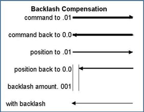
-
- Gearing
- Ball screw nuts
- Ball screw support bearings
- Rack and pinions
- Couplings
- Loose components
- Flexing components
If the backlash is repeatable, it can be compensated for by adding an additional movement to the axis, equal to the amount of the backlash, whenever the axis reverses. Backlash compensation can be measured and adjusted using a dial indicator, or the results of an interferometer or ball bar report.
Sometimes backlash varies depending on whether the machine was feeding or in rapid traverse due to the dynamics of the machine. In this case, two different fixed backlash amounts can be used - backlash compensation for feed and rapid.
With the above features, the total backlash compensation is output at the position where the direction of axis movement reverses.
Using another feature called smooth backlash compensation, backlash compensation can be output more gradually. With smooth backlash compensation, there is an initial backlash 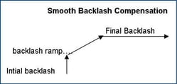 compensation (like in normal backlash compensation) and then a ramp up to a final compensation value based on a distance traveled from the axis reversal point. Again, this is set based on the dynamics of the machine.
When using linear scales for feedback, backlash error should not exist since the control is reading its position directly from the scale that is mounted directly to the slide, thereby by-passing any mechanical deficiencies. If there is backlash it is usally backlash in the linear scale, typically caused by a loose or flexing reader head or yaw.
PITCH ERROR COMPENSATION
Absolute positioning of a machine tool is subject to errors in the manufacturing of the machine's components. All ball screws or gearing have lead (pitch) errors. Even linear scales and encoders are not perfect and have inherent manufacturing errors.
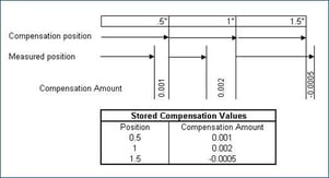
Using a laser interferometer, these errors can be measured at fixed intervals. The errors are then stored in the control and when an axis reaches a specific position, the stored value for that position is added or subtracted to the axis motion, thereby reducing the positioning error.
When the amount of pitch error compensation varies for a particular position, depending on the direction of axis movement (usually due to wear on the ball screw or gear rack in the work zone), normal backlash / pitch error compensation can only average the reversal error. In this case, another feature called bi-directional pitch error compensation is useful. Similar to regular pitch error compensation, a laser interferometer is used to measure errors at fixed position intervals. However, with bi-directional pitch error, two tables are generated - one for each direction. This helps compensate for varying errors based on both position and direction.
With the above features, the total position error compensation is output at each fixed interval (usually .5" - 1"). Using another feature called interpolated pitch error compensation, position error is divided into smaller increments which effectively creates a straight line between compensation intervals and smoothes out the error compensation output.
Older controls had very limited amounts of table storage for pitch error compensation, usually 128 point per axis. With options, newer controls have 1,536 points that can be divided among the axes. If bi-directional pitch error compensation is used, additional points can be installed.
INCLINATION COMPENSATION
If an axis has a positioning error that follows a trend, three approximate straight lines can be determined using (4) pitch error table compensation points. This helps reduce the total number of pitch error table compensation points used. Inclination compensation is superimposed on the stored pitch error compensation at pitch error intervals.
The trends are based on laser interferometer values.
PERIODIC SECONDARY PITCH ERROR COMPENSATION
Any time a rotating element is used, a cyclical error occurs due to the imperfections per revolution. This is most obvious with pinions such as one moving a rotary table but can also appear on a linear axis.
The secondary interval is always less than or equal to one (1) pitch error interval and is superimposed on the pitch error compensation.
These errors are measured with a laser interferometer.
STRAIGHTNESS COMPENSATION
Sometimes, when one axis is moved, another axis position changes. This can be seen when a horizontal milling machine bar is extended. Extending the bar in the (Z-) direction causes the end of the bar to droop from its weight in the (Y-) direction. Another example would be a vertical lathe or a gantry type machine. When the saddle is moved towards the center, the machine sags due to the weight of the saddle causing a change in the (Z-) axis. The Straightness Compensation option will compensate one axis based on the position of another axis.
With the above features, all error compensation is output at each fixed interval. Using another feature called interpolated straightness compensation, position error is divided into smaller increments which effectively creates a straight line between compensation intervals and smoothes out the error compensation output.
Measurement is usually done with a dial indicator.
THREE DIMENSIONAL ERROR COMPENSATION
Three dimensional error compensation is also known as volumetric compensation. It takes into account pitch, yaw, roll, positioning, straightness, etc.
In its simplest form, the machine work envelope is divided into cubes. The corner (vortex) of each cube is a point with known error compensation values. The actual error compensation is then determined by using ratios from the known points to the current position.
Volumetric error measurements are usually done with a laser tracker.
THERMAL GROWTH COMPENSATION ALONG TOOL VECTOR
On 5-axes machines, thermal growth compensation can be applied along the tool vector. This feature determines a thermal growth value based on a number from the PMC and applies it in the tool axis direction.
The PMC determines this number based on temperature sensors and machine/process specific algorithms for a given machine tool.
FANUC Tips & Tricks
To delete a line from your NC program, place the cursor at the beginning of the line, hit the "eob" key followed by the "delete" key.
Did you know? FANUC can produce 20,000 controls and 100,000 servos per month!


